ID-5001 LED Backlight Conversion
Version 3 with Linrose Super Brite White LED
Strips
Overview
The LED backlight conversion replaces the fluorescent lamp with LED strips of
equilavent brightness and greater reliability. The upgrade process
involves disabling the fluorescent circuit on the power supply board, removing
fluorescent lamp sockets, building the LED "board", and mounting a socket for a
2.1mm 12VDC power supply plug on the back of chassis.
The steps provide sufficient information for the experienced eletronics
hobbist.
Figure 1. Power Supply Board Modifications
Original Power Supply Circuit
Board (1987)
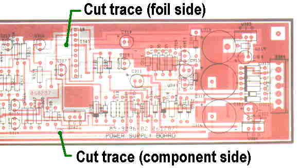
Updated Power Supply Circuit Board (1989)
Parts
| Part number |
Description |
Quantity |
Unit Price* |
| B26LSM4-12V |
LED Flex Strip - 26 white surface mount LEDs |
2 |
$19.90 |
Other parts:
- 1" by 10" rigid plastic backer (approx. 0.05" thick)
- 12" of red 22 AWG wire, 12" of black 22 AWG wire
- Double-sided foam tape (alternately use hook-and-loop fastener -- e.g.,
Velcro).
- 12VDC 1A regulated power supply (e.g.,
Example)
- 5.5mm x 2.1mm DC Power Jack Socket Female Panel Mount Connector (e.g.,
Example)
* Prices may vary.
Assembly Instructions
Disassembly
- Disconnect ID-5001 from the wall power.
- Remove main cover and lamp cover.
- Remove the main circuit and power supply boards.
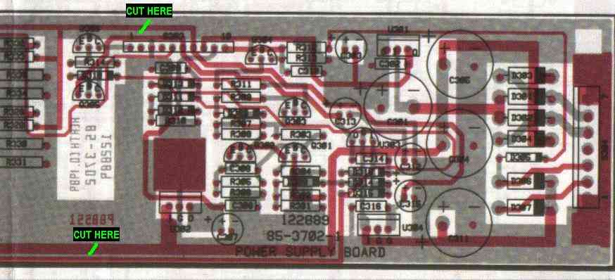
- Cut the two traces that supply power to
the fluorescent lamp (see Figure 3).
- Remove the lamp cover plate.
- Remove fluorescent lamp and lamp sockets.
- Reinstall the power supply and main circuit boards (see note for step 1
below).
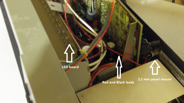
LED Board (refer to Figures 2 and 3)
- Mount the 2.1 mm Power Jack Socket Female Panel Mount Connector to the back of the chassis near where the AC power cord enters.
Note: it may be easier to mount the connector prior to reinstalling the
power supply and main circuit boards.
- Prepare 1" by 10" rigid plastic backer.
- Cut both LED strips to about 10" (cut strip only where indicated by the
markings on the strip itself).
- Remove LED strip backing to expose the adhesive. Affix to the
plastic backer.
- Prepare 10" red and black leads. Remove 1/4" insulation from each
end.
- Solder one end of the red 12" lead to the positive (+) solder point on
one end of the first LED strip.
- Solder one end of the black 12" lead to the negative (-) solder point on
one end of the first LED strip.
- Prepare 2" red and black leads. Remove 1/4" insulation from each
end.
- Solder one end of the 2" red lead to the positive (+) solder point on
one end of the second LED strip. Solder the other end of 2" red lead
to the same solder point in step 6.
- Solder one end of the 2" black lead to the negative (-) solder point on
one end of the second LED strip. Solder the other end of 2" black lead
to the same solder point in step 7.
- Apply 1" pieces of double-sided foam tape to both ends of the back the
plastic backer.
- Affix the plastic backer to the inside the light chamber in the previous
location of the fluorescent bulb. Route the red
and black leads through the gap between the sides of the light chamber to
the back of the chassis where the female 2.1 mm adpater is mounted and
solder the leads.
- Replace the light cover.
- Apply 12VDC to verify light operation.
- Replace chassis cover.
- Apply AC power.
Figure 2. The LED board assembly
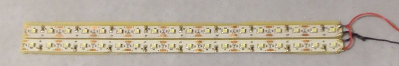
Figure 3. Final assembly
Disclaimers
Thunderhead
Technologies assumes no responsibly for the accuracy of the
ID-5001 LED Backlighting Conversion, availability of its
parts, its fitness for any purpose, or any damages - direct or
inconsequential - to persons or property.
The ID-5001 LED Backlighting Conversion is intended for
individuals experienced in electronics assembly. Consult a
qualified professional if you are unsure of your ability to
perform the required steps. Always follow safe practices while
working with electronics including wearing an anti-static wrist
strap to avoid damage to any electronic component.
Use of any vendors' parts does not constitute an endorsement of
that vendor.
Note: The LEDs will likely begin to very slowly dim after about 12 months.
Replace the LED strips to restore full brightness.
Last updated: November 4, 2016